The chair is now complete and in use! If anyone has any questions you can email me via the contact form (comments were abused so I turned them off).
Here are a couple of diagrams showing how I put the parts together – you need to refer to parts #1 (plus update), #2, and #3 (plus update) for this to make sense, of course.
First of all, this is the seating section (the seating plate attaches to the top).
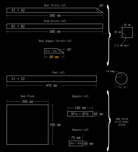
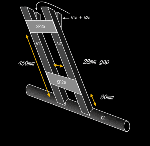 To put it together, I used a pair of small G-clamps to hold to spacers (SP2a and SP2b) in the positions I had determined for them on one of the struts (A1). I made a weld along one edge so I could get the clamps out of the way, then finished off the welding in a vice. Then, I used the G-clamps again to hold the other strut (A2) in place – I used a mallet to knock it into position to obtain the correct spacing (so my screw-adjust riser would fit). Note that at this stage I also made sure the curved bottom ends were level with each other so the foot (C1) would be horizontal. Then I made the welds as described above.
 I used a pair of powerful welding magnets to hold the foot (C1) in place while I welded it in place.
I made sure the 45º angle cuts were level with each other (just a little filing was needed to get the Seat Plate to sit level), then I used the welding magnets to hold it in place while I welded it.
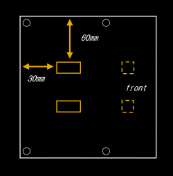
Once the seat plate was welded in place (see diagram opposite for placement), I was able to slide in the Seat Support Struts (A1a and A2a) – again holding them in place using the magnets. They actually fit almost perfectly, but I did a little trimming to make sure I got the best fit possible. In each case I welded one side so I could get the magnetic clamps out of the way, then finished off the whole weld (all four sides) in a vice. Note that the dotted squares in the diagram show the approximate placing of the struts on the Seat Plate.
Next, the Knee Section. This is a little easier – note that I originally planned to use two spacers on this section, but I didn’t allow for having to slot the Seating Section through it, and a spacer higher up would have got in the way.
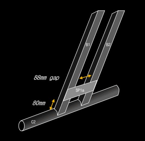 I assembled this in more or less the same way as the Seating Section. Initially, I clamped the spacer (SP1a) in place on one strut (B1) and did a single weld, then finished it off in the vice with the G-clamp out of the way. Then I positioned the other strut (B2), making sure the curved cut-out was level with the other one (for the foot) and that the spacing was correct along the whole length. Then I welded it. I welded on the foot as described for the seating section.
I used my angle grinder and a flap wheel to grind down all the welds and to remove spatter.
Next came the test assembly. Omitting the second spacer from the Kneeling Section had the additional benefit of allowing a little flexibility when it came to sliding the Seating Section between the kneeling struts. But I’d got it right and everything fit. I did have to do a little widening of the holes to get the bolts through – with hindsight I would have drilled after welding (unless you are millimetre perfect there is always going to be a slight mis-alignment).
I painted all the parts using Hammerite Metallic Black (from a tin). I inititially tried Hammerite Silver (from aerosol), but apart from the fact it doesn’t fill in imperfections very well, it also looks a bit cheap – too silver, if you ask me! It also makes a bloody mess.
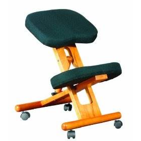
This is the finished stool, fully painted and assembled. You can see how the riser mechanism fits between two sets of holes, and the other set is where the two sections are joined.
 You can also see the crappy cushions I am using at the moment – the final stage of this project is going to be to make a decent pair (I’ve found a great company called eFoam who can cut foam to measure).
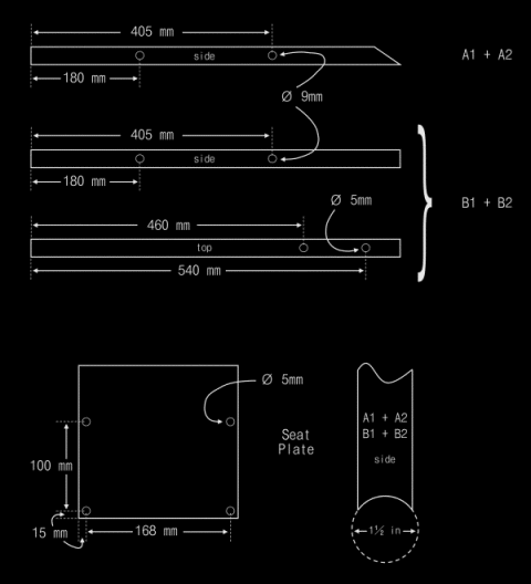 Don’t forget that I am using some of the parts from my existing chair, and that explains some of the oddities (e.g. the 9mm holes, the hole spacings on the seat plate, and so on).
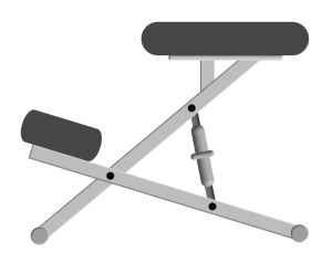
 I spent today (had most of the day off in order to get this going) trimming the parts. Last week I used an angle grinder to take the 3m lengths of 30mm box and 1½” round steel sections down to manageable pieces. The diagram below shows roughly how the parts will fit together – I’ll put up a better drawing with dimensions later.
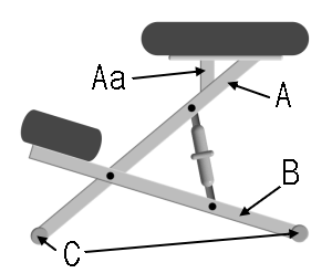 Basically, there are two seat struts (A) parallel to each other, and two knee struts (B) the same. The seat struts are closer together and fit inside the knee struts in a distorted X shape. I’ll use the spacers to make sure that the struts are the right distance apart.
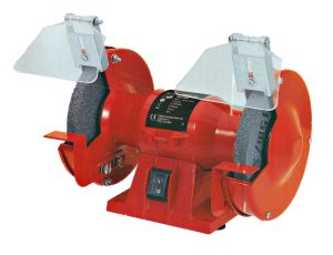 Makro stocks a wide range of tools, especially the Fairline range. In the original post
  metal slightly. This eventually leads to fractures along lines of weakness – either the weld or across the strut itself. It’s all about cutting costs to save money as far as the manufacturers are concerned.
 3 metres of 1½” x 14swg mild steel tube for the floor spars
 After my irritation at
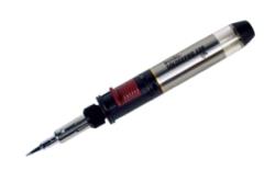
 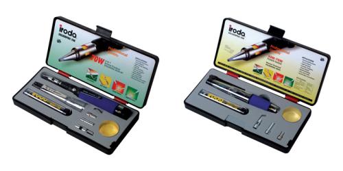 If you’re looking for a soldering iron and always thought – as I did – that cordless ones were pretty pathetic (some of them are), then this is really worth looking into.